Optimizing Roof Trusses for Bracing
TYLER RHODES
For educational purposes only - always consult a licensed engineer for project-specific design decisions.
INTRODUCTION
Truss design software analyzes components to handle in-plane loads. These are loads applied to trusses within two dimensions you see on a truss drawing - up/down and left/right. In reality, wood roof trusses are thin members which can buckle easily if not reinforced, which is why bracing is so necessary. Truss designers often don’t consider how their design choices can impact the ease and safety of bracing in the field. The goal of this guide is to help designers understand the basics of bracing, and learn tips for optimizing it for the field.
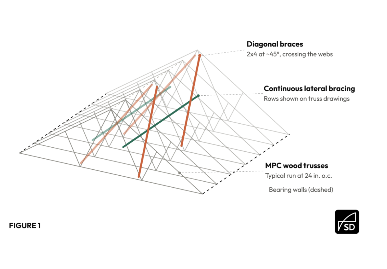
There are two types of continuous, permanent bracing applied to webs (reference Figure 1). Temporary bracing, chord bracing, and specialty bracing are outside the scope of this article.
TYPES OF BRACING
Continuous lateral bracing is often specified on truss design drawings. Most truss design software automatically calculates locations where lateral bracing is required to prevent webs from buckling, but additional bracing locations can also be specified by the component engineer or the engineer of record on a bracing plan. This is what a lateral brace specification could look like on a truss design drawing:
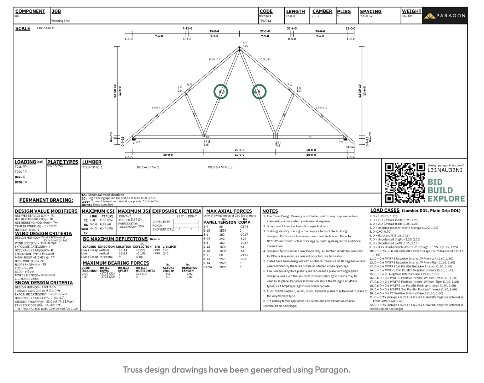
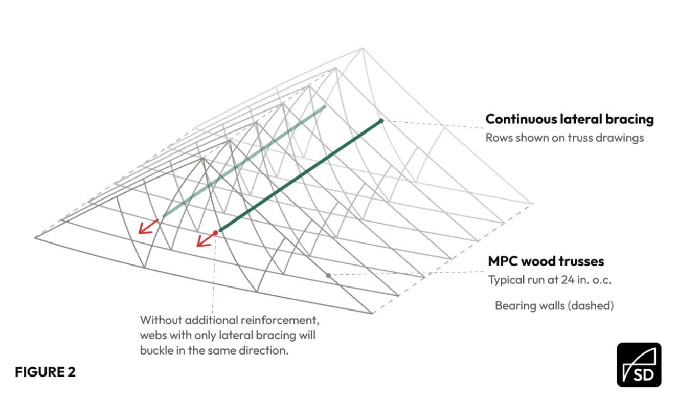
When there is a single lateral brace specified on a truss web, it is placed at the midpoint between the two connected joints, but it can be placed on either side of the web in question. If a web is at 100% stress for buckling in the out-of-plane axis, placing a support at the midpoint, in theory, reduces the effective buckling length by half, which drops the stress ratio to roughly 25%. However, this relies on the assumption that this brace is fixed and stable. If all the trusses in a run are the same profile, and only lateral braces perpendicular to the trusses are installed, there is nothing stopping all webs from buckling in the same way (reference Figure 2). That’s where diagonal braces come in…
Diagonal braces are installed on the same row of webs as the lateral bracing, but at a 45-degree angle. Anchoring the diagonal bracing at different points on each truss provides rigidity and allows stress built up from the rows of lateral bracing to transfer into the building’s diaphragm.
T-Bracing or L-Bracing can be utilized in situations where diagonal or lateral bracing is impractical (such as hip roofs), but designers should note that this usually requires more bracing lumber and fasteners when trusses are spaced at 24” on center. You can read more about substituting continuous braces with T-braces in NFBA’s article on the subject (linked in Further Reading section).
As truss designers/technicians, we don’t have a responsibility to design a bracing plan (nor the authority), but that doesn’t mean we can’t make it easier for others to design or place bracing. We can make bracing easier and safer through our design decisions.
IMPORTANCE OF ALIGNING WEBS
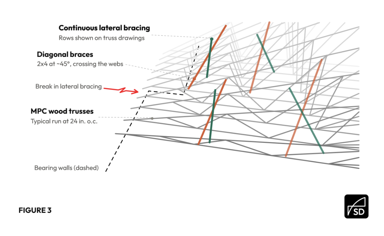
Designers often fall into the trap of treating truss design as only a material optimization problem, and as a result will often choose the cheapest webbing pattern for every truss, regardless of the difficulty it may cause in the field. In some situations, it is impractical to align webs, but in many situations such as a simple difference in bearing location, the cheap and easy solution to align webbing patterns is missed. This makes installing bracing (or designing a bracing plan) more complicated, and reduces the rigidity of the overall structure. See in Figure 3 how the designer chose the default webbing option for each truss. As a result, the line of lateral bracing is broken, and the diagonal bracing will only share diaphragm loading with neighboring trusses of similar webbing patterns.
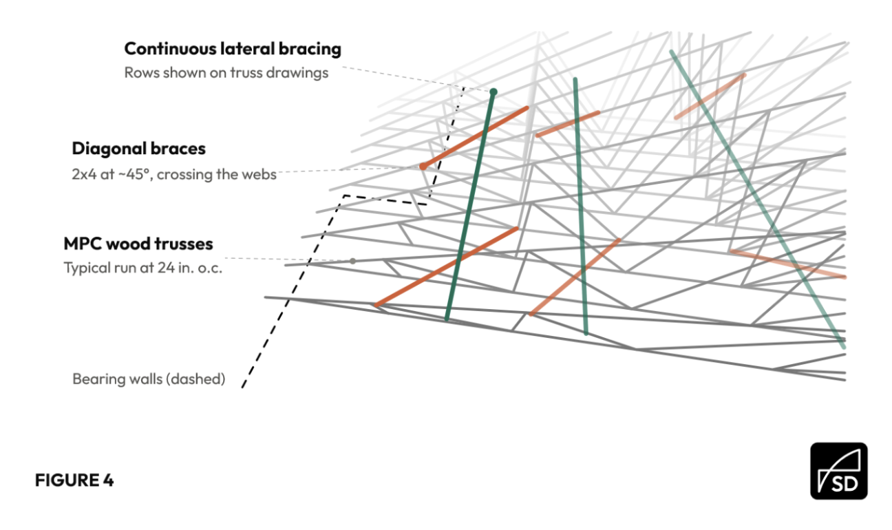
By contrast, the designer for the trusses in Figure 4 chose to think about the optimization of the structure as a whole. If an engineer is designing a specialized bracing plan, he/she can prescribe a repeatable solution across the roof, and the carpenters can install simple and continuous patterns. Most importantly, the structure is more rigid and can withstand diaphragm loads more effectively.
Some truss design software has features where you can overlay trusses to ensure webs are aligned, but even if the process is more manual and takes a couple extra minutes of your time, aligning webs where possible can make a big difference down the road.
MEMBERS IN TENSION VS COMPRESSION
Part of optimizing trusses for bracing is eliminating bracing where it isn’t needed. One area where lateral bracing can often be removed is at raised-heel locations. See in the truss design drawing how the last webs sloping down to connect to the bearing joints are specified with two rows of lateral bracing each. Forces from truss loading accumulate at this last panel and often result in a large compression stress in the last web when it is in this orientation.
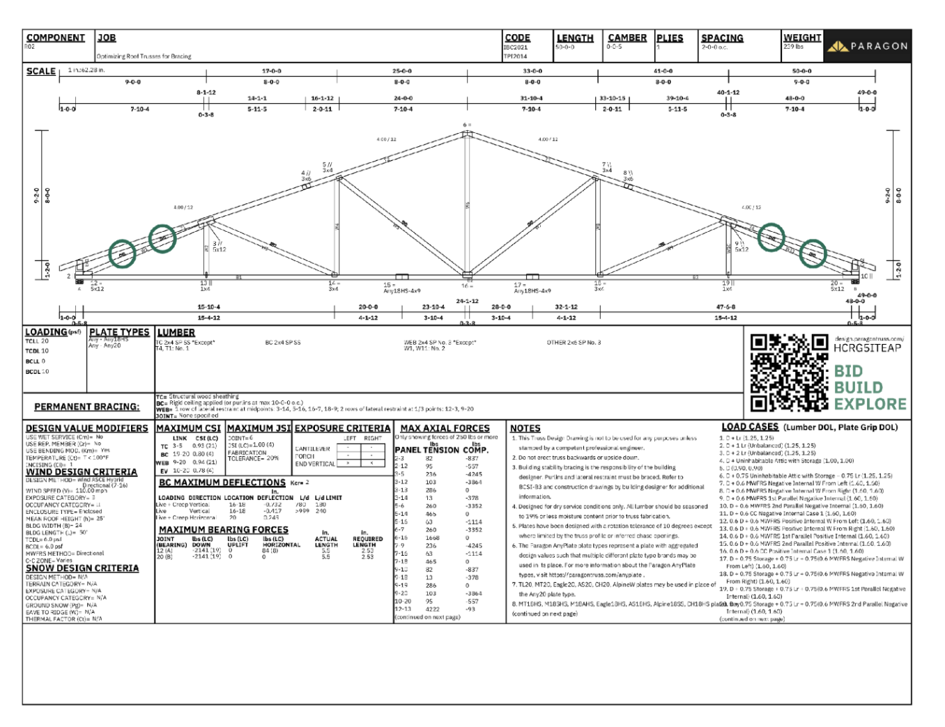
When bracing like this is specified on a truss drawing, there is a very real possibility that only one lateral brace will be installed, or it will be missed altogether because of the inaccessibility of the location. Some engineers feel uncomfortable with two rows of lateral bracing on a single web for this reason.
One simple solution is to reverse the orientation of these webs, so they are in tension instead of compression. This will often remove these extra lateral restraints so lateral bracing is only needed at the more open panels in the truss.
See in Figure 5 the difference in tension and compression of the same truss profile with this slight adjustment to the webbing pattern (Load case #1: D + Lr shown). Note that this graphic is under simple gravity loads, and lateral bracing will only be eliminated if the web member does not have critical compression in other load cases with unbalanced loads and wind uplift loads. In the case of the truss drawing attached, those additional load cases did not add enough compression to add lateral bracing, but results will differ based on the condition.
REFERENCES
American Wood Council, National Design Specification (NDS) for Wood Construction, ANSI/AWC NDS-2024, Leesburg, VA, 2024.
Structural Building Components Association and Truss Plate Institute, Building Component Safety Information (BCSI): Guide to Good Practice for Handling, Installing, Restraining & Bracing of Metal Plate Connected Wood Trusses, 2025 ed. — see Chapter B3, "Permanent Restraint/Bracing of Chords & Web Members."
Truss Plate Institute, ANSI/TPI 1: National Design Standard for Metal Plate Connected Wood Truss Construction, ANSI/TPI 1-2022, Alexandria, VA, 2022.
FURTHER READING
Anderson, C., F.E. Woeste, and D.A. Bender, "Substituting T-braces for Continuous Lateral Braces on Wood Truss Webs," Frame Building News, June 2002, pp. 36–40. https://nfba.org/aws/NFBA/asset_manager/get_file/796296?ver=0 (accessed July 2026).
Underwood, C.R., F.E. Woeste, J.D. Dolan, and S.M. Holzer, "Permanent Bracing Design for MPC Wood Roof Truss Webs and Chords," Forest Products Journal, 51(7/8):73–81, 2001.
Wood Truss Council of America (WTCA, now SBCA), Bracing Webs in Trusses that have Dissimilar Configurations, Tech Note T-DissimilarWebs06, April 25, 2006.
Truss design drawings featured in this article were generated using Paragon truss design software. https://www.paragontruss.com/
Standards and industry guides are revised periodically — always refer to the current editions and the editions adopted in your jurisdiction.